
Page 38 - Zmist-n2-2015
P. 38
Welding parameters such as tool rota-
tional speed, traverse speed and axial force
play a major role in deciding the weld qua-
lity. Experiments were carried out to join
the AZ91D magnesium alloy plates of size
100 mm (length) × 100 mm (width) × 6 mm
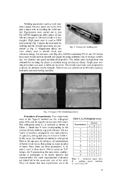
(height). High speed steel is used as FSW
tool material. Fig. 1 shows the tool used for
welding and the welded specimens are pre-
Fig. 1. Friction stir welding tool.
sented in Fig. 2. Magnesium alloys are
most widely used to absorb shock and
vibration energy. For instance, cast Mg alloy AZ91D containing 9% Al and 1% Zn has
been most widely used in aircraft and engine building industries due to its high castabi-
lity, low density, and good mechanical properties. The initial joint configuration was
obtained by securing the plates in position using mechanical clamp. Single pass wel-
ding procedure was used to fabricate the joints. The tensile specimens were prepared to
evaluate the ultimate tensile strength. Tensile test was carried out in 60 tones capacity,
hydraulic universal testing machine.
Fig. 2. Images of the welded specimens.
Procedure of experiments. Two major tools
used in the Taguchi method are the orthogonal Table 1. L 9 Orthogonal array
array (OA) and the signal to noise ratio (S/N ratio). Factors
The orthogonal array L 9 is selected as shown in Experiments
A B C
Table 1, which has 9 rows corresponding to the
1 1 1 1
number of tests with the required columns. OA is a
matrix of numbers arranged in rows and columns. 2 1 2 2
A typical L 9 orthogonal array is shown in Table 1. 3 1 3 3
In this array, the columns are mutually orthogonal. 4 2 1 2
That is, for any pair of columns, all combinations
5 2 2 3
of factor levels occur, thus giving an equal number
6 2 3 1
of times. Here, there are three parameters: A, B,
7 3 1 3
and C, each at three levels. This is called an “L9”
design, the 9 representing the nine rows, configu- 8 3 2 1
rations or prototypes to be tested. Specific test 9 3 3 2
characteristics for each experimental evaluation Note: A – rotational speed, rpm;
are identified in the associated row of the table. B – welding speed, mm/min;
Thus, L9 means that nine experiments are to be C – axial force, kN.
37